 store
store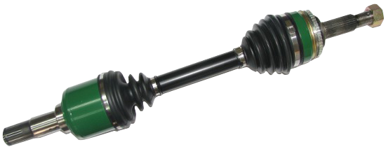
Fiat 126/500 : tripod cv joints mounting instruction
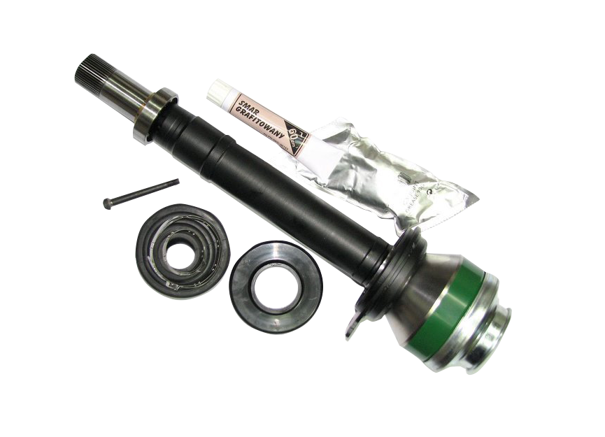
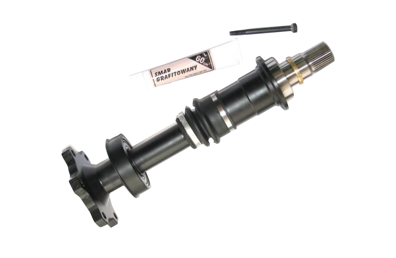
The set consists of following elements:
- joint trunk
- tripod
- self-locking nut
- rubber snubber
- spacer pipe
- joint boot with clamps
- two packets of grease
I.
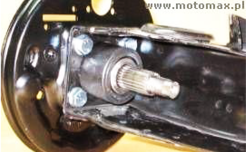
- Completely disassemble the trailing arm hub assembly. Check the trailing arm for damage or cracks. If damaged or cracked, repair or replace trailing arm.
- Check both bearings and stub axle shaft for wear. If there is any sign of wear on the stub axle, or if the bearings are noisy replace these items before proceeding.
II.
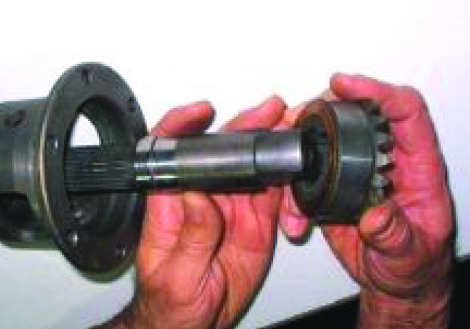
- Install the tripod housing on to the splined portion of the stub axle. You may have to tap it on with a hammer. Leave the wire ring on the tripod housing, you will need it later.
III.
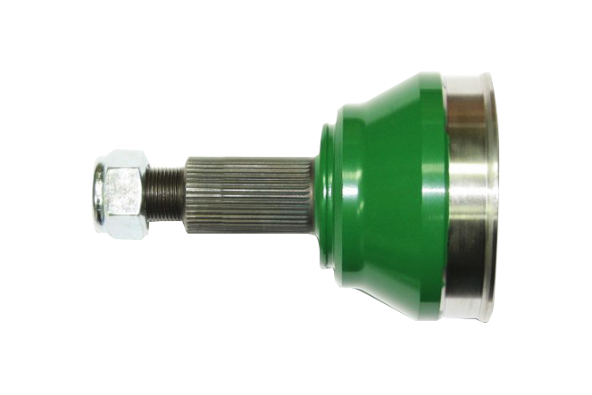
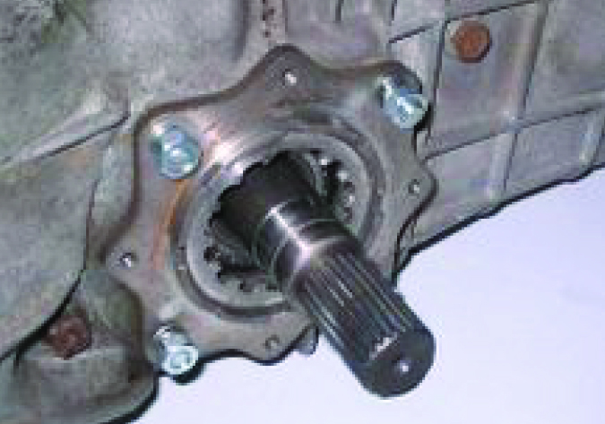
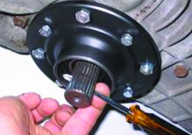
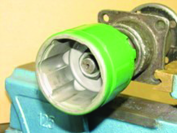
- Attach the tripod housing to the stub axle using the provided 27mm nyloc self-locking nut.
Tighten the nut to the factory recommended torque. Be sure to check the bearing preload and make sure the axle rotates freely.
IV.
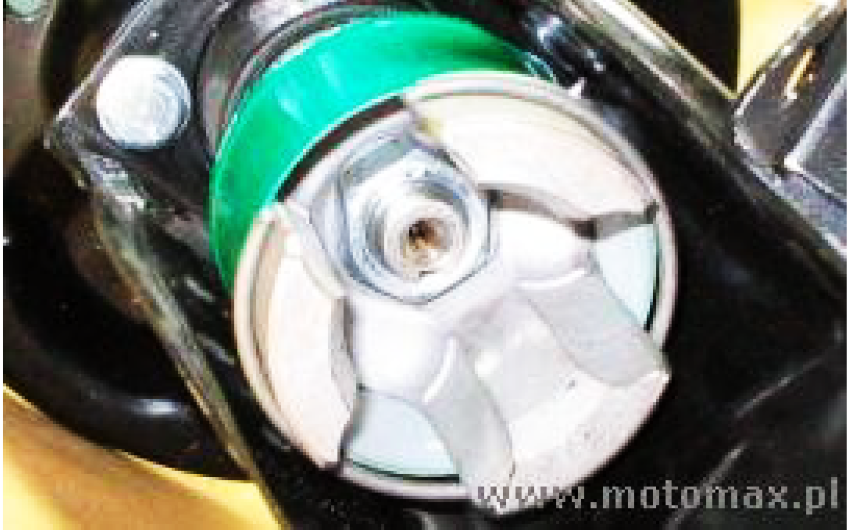
- Fill the tripod housing with the grease from one of the two packets.
- Install the rubber snubber into the opening on the end of axle shaft.
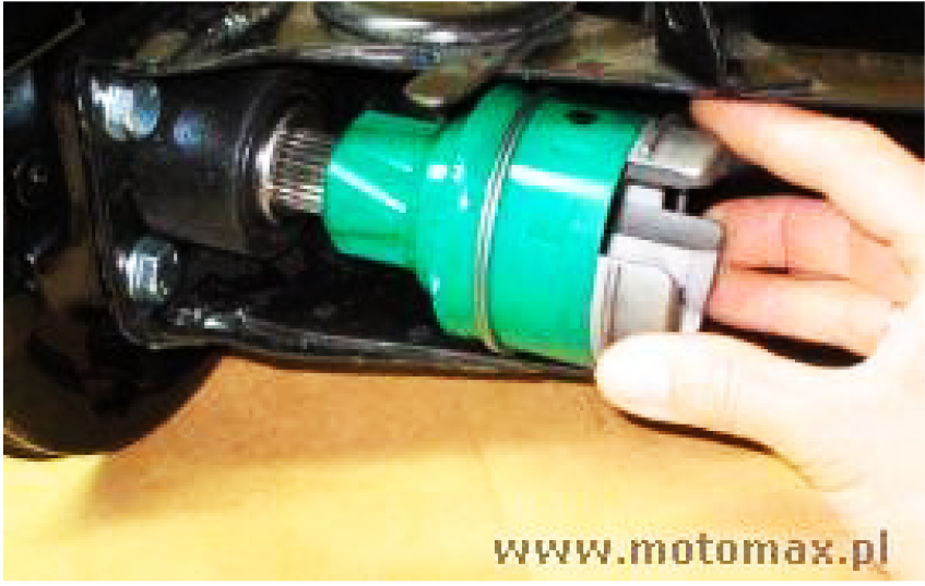
- Install the listed items in the following order: Rubber boot first (small end first), then spacer, and finally the tripod joint itself (Make sure the recessed side of the tripod joint faces toward the end of the axle.
- Place circlip in groove at the end of the axle.
- Push the axle into the gearbox far enough to allow the splined end to be passed through one of the slots in the tripod housing. (You may to push out the gearbox.)
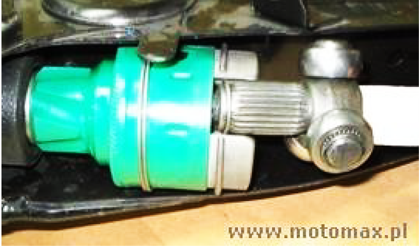
V.
- Slide the tripod and spacer forward and into the tripod housing until the tripod is in contact with the circlip. 11. Fill the boot with grease from the second grease packet.
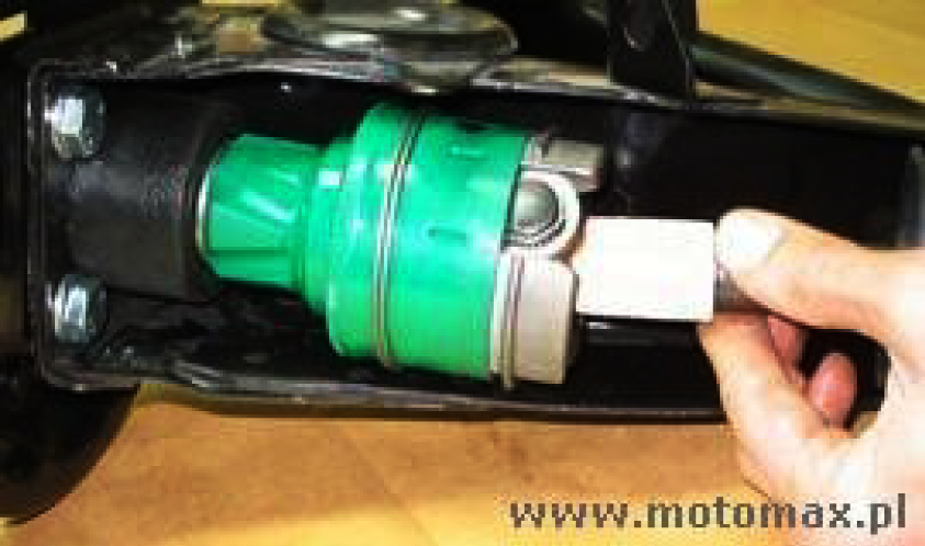
VI.
- Slide rubber boot onto the tripod housing so that it is past the retaining ridge in the housing.
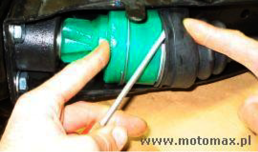
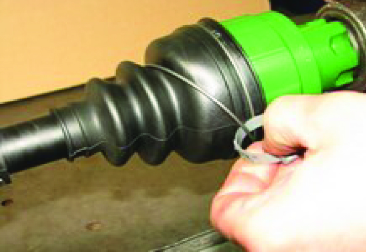
VII.
- Place one end of the wire boot retaining ring onto the rubber boot, and using the small retaining ring as a guide, rotate the axle until the wire boot ring is completely on the rubber boot. This will install the wire ring without damaging the rubber boot.
VIII.
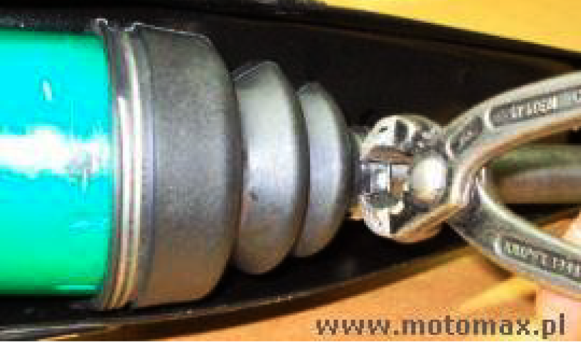
- Adjust the small boot clamp for the size of the inner boot diameter and place on boot.
- Slide clamp and rubber boot assembly so that it is against the plastic washer and spacer (this holds the tripod in position on the end of the axle).
- Compress the small metal clamp with a set of pinch pliers.
IX.
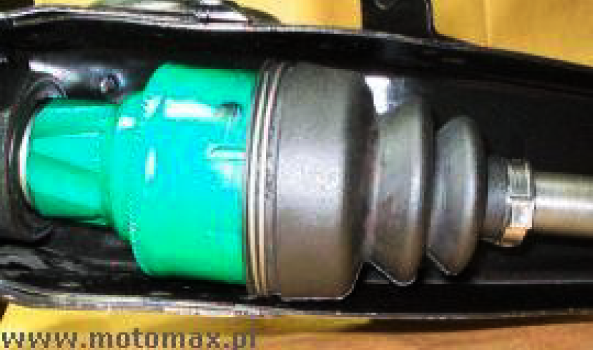
- This completes the installation. Turn the axle to insure that it does not touch the trailing arm.
- You should have 5mm clearance between the installed tripod joint and the upper and lower surface of the trailing arm.
Fiat 126/500 driveshafts with gearbox side joints mounting instruction:
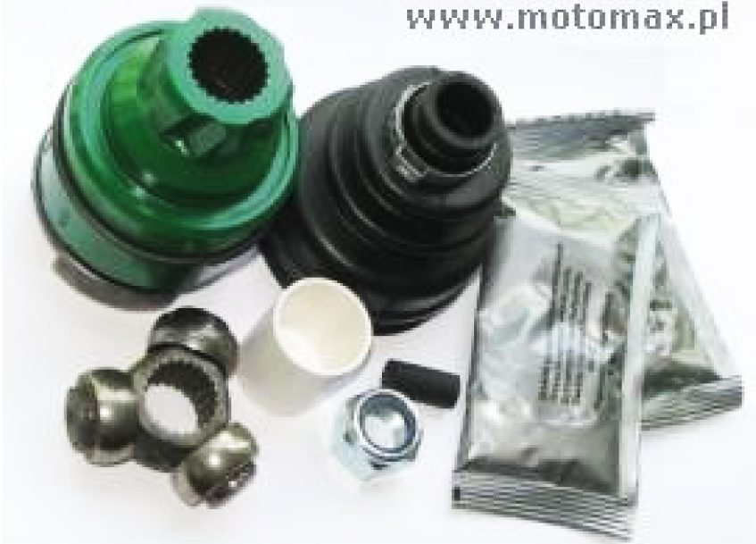
I.
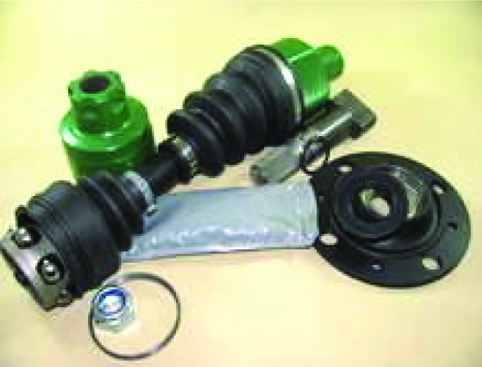
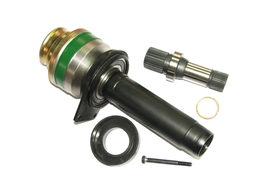
- The single-side (set half) contains with: Interconnecting axle with inner tripod joint and outer B-F cv joint, sideplate with bearing, stub axle, seal, seeger circlip, outer joint’s boot clamps, grease and nyloc nut.
II.
- Dismount the differential mechanism with half-shafts from the gearbox body.
- Disassemble the differential mechanism, and remove the half-shafts with the “stones”.
- Introduce the stub axles into the differential side (crown) gears.
III.
- Assemble the differential casing with original bearing covers
- Regulate precisely the side bearing tension and final drive clearance. (!!!)
IV.
- Install the side bearing carriers (included in the set). - Take an attention to the o-ring position (!), and screw tight the M6 bolts.
- Pull out the stub axle, using the hole in the splined end. Fix the stub axle in the right position by seeger circlip
- Place the seal rings in the side plates casing.
- Repeat the stub axle installation process for other side of the car.
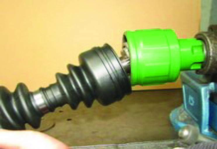
V.
- Install the joint housing on to the splined part of the stub axle. You may have to tap it on with a hammer.
- Attach the joint housing to the stub axle using the provided 27mm nyloc self-locking nut. Apply the nyloc nut with the locking ring FIRST! (opposite to standard use).
- Tighten the nut to the factory recommended torque. Be sure to check the bearing preload and make sure the axle rotates freely
VI.
- Check the rubber damper is placed in the hole at the end of the axle shaft.
- Fill up the joint housing with a half of the grease volume, and introduce the joint ball-cage into the housing.
VII.
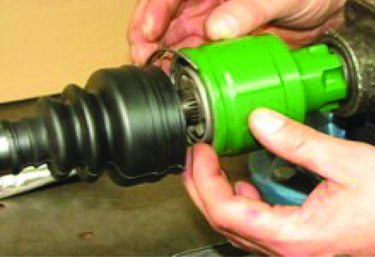
- Install the wire ring into the channel inside the joint housing to keep the ball-cache on place.
VIII.
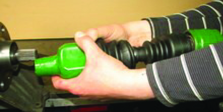
- Install the inner joint of the driveshaft onto the gearbox stub axle, pulling the joint to outside direction. (There is a spring inside the joint).
IX.
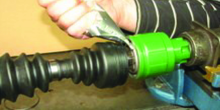
- Fill the joint housing and the cv joint boot with second half of grease.
X.
- Fill the joint housing and the cv joint boot with second half of grease.
- Place one end of the wire clamp ring onto the clamp place, and using the small clamp as a guide, rotate the axle until the wire ring is completely on place . This will install the wire ring without damaging the rubber boot.
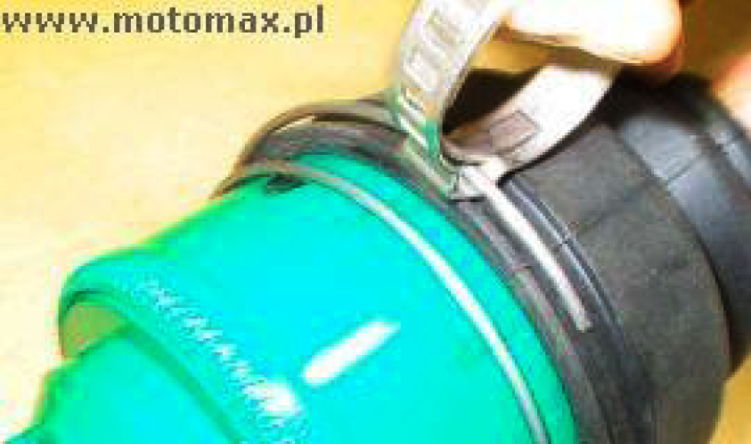
XI.
- Close the shaft side of the joint boot with a universal clamp
- Repeat the joint installation process for other side of the car